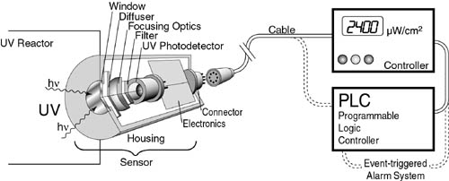
Figure 1. Schematic of an on-line radiometer
Enviro Process Engineering (HK) Co. Ltd.
安和環保工程(香港)有限公司
Understanding UV Monitoring for Air and Water UV Treatments
Authors:
José Goin, Pharm. D., PhD, Apprise Vice President
Anatoly Skirda, PhD, Apprise Senior Electronics Engineer
Eugene Tohktuev, Apprise Director of Development and Engineering
INTRODUCTION
During the past few years we have seen a significant increase in different industrial processes based on the use of Ultraviolet Radiation (UV)1. Disinfection of water, air or foods; fast curing of inks, glues and coatings; and elimination of pollutants are all processes that may use UV as the primary energy source to “get the job done”.
For a process like UV curing, where the target is a surface, the correct term to express the incident UV power is Irradiance. For processes like disinfection or decontamination, where the target is a particle (bacteria, virus, toxic compound, etc.) suspended in a fluid (water, air), the correct term to express the incident UV power is Fluence Rate2. Both Irradiance and Fluence Rate are expressed in units of power per unit of surface, or W/m2 or mW/cm2 (1 mW/cm2 = 10 W/m2)
UV processes like fluids disinfection, curing, etc. all require specific “amounts of UV” or Energy Density in order to be realized. Commonly described as “UV Dose” (also called “Fluence”), these “amounts of UV” are the product of the power of the UV radiation times the time the surface or the particle is exposed to the UV radiation.
Thus, UV Dose is the total amount of UV energy incident on a certain area in a certain period of time. The units of UV Dose are J/cm2, which is defined as the irradiance or fluence rate of the UV radiation (in Watts) multiplied by the time the material was exposed to such radiation (in seconds) per unit of area:
UV Dose = UV Power Density x Exposure Time
or
mJ/cm2 = mW/cm2 x seconds
The effectiveness of each of these applications relies primarily on subjecting the material to be treated (i.e., water, air, glue, ink, etc) to a certain UV Dose. For most of the applications, a minimum dose needs to be guaranteed, while in some cases a maximum dose also needs to be avoided (overexposing inks and other substrates to UV radiation may be as bad as underexposing them).
In addition, since time is directly proportional to the cost of these processes, it is important to minimize the exposure time to the UV radiation to make the process faster and cost-effective. Given a certain UV radiation source, identifying the minimum exposure time required to reach the desired effect for a certain process is critical.
To maintain a certain effective dose for a given process, the operator must carefully monitor the intensity or irradiance of the UV radiation as well as the UV exposure time. UV lamp aging, unexpected water quality change, biofouling and other factors may produce a decrease in the irradiance. In order to maintain a certain UV dose if the irradiance decreases, the operator will then have to increase the exposure time accordingly (i.e., decrease the flow rate of air or water in the disinfection reactor, increase the “oven time” for a UV batch exposure of electronic assembly parts, etc.) or simply increase the irradiance by modulating its output (applicable only to some types of lamps) or replacing the aged UV source.
Therefore, the constant monitoring of the irradiance is of primary importance.
UV monitoring systems for different applications are commercially available. However, the selection of the proper monitoring equipment can significantly impact how efficiently the irradiance is controlled. An improper selection of the UV sensor system can lead to the inability of the user to control the output of the UV-related process. This is even more important when the output of the process cannot be tested in real time (i.e., disinfection).
In UV processes, such as the curing of coatings and surface disinfection, the target is a surface. Monitoring the process in which a surface is being treated involves subjecting the UV monitoring device to the UV treatment process. The unit will report irradiance values (Radiometer) or, if the unit is capable of integrating the data being measured over the time of the process, it will also report the UV Energy accumulated at the surface, or the UV dose (Dosimeter).
In fluid treatments (air, water, etc.), it is impossible to individually monitor the UV energy absorbed by every single particle passing through the system. In addition, the particles will follow different “routes” within the reactor and therefore will absorb different amounts of UV energy. The process can be monitored using an on-line radiometer that will monitor the irradiance produced by the UV lamp(s) from one or multiple fixed points. It is important to understand that on-line radiometers3 are not at the target position and therefore do not measure directly the UV process.
During the development of a UV treatment system, most companies consider sensor selection and development an easy task, and usually assign it to a mechanical or an electrical engineer. This is mostly done because few companies have staff who are experts in modern optics. The result is often poorly designed monitoring units that do not perform as required.
From the manufacturer’s end, when a water or air UV treatment system is being developed, it is important to include in its design an appropriate sensor system that will monitor the process. From the user’s point of view, it is important to understand the capabilities and limitations of the sensor, even if this process leads to the discovery that the sensor unit is badly designed and cannot monitor the UV process with the required efficiency.
There are several critical factors to take into account when selecting an on-line radiometer. In order to evaluate each of them, it is necessary to understand the elements of an on-line UV monitoring unit. Depending on the UV system being monitored, the elements may or may not be present in the sensor.
ELEMENTS OF AN ON-LINE RADIOMETER:
Defined as an optoelectronic sensor, an on-line radiometer (Figure 1) has three basic components: The Mechanics, the Optical Assembly Module, and the Electronic Signal-Processing Module.
Figure 1. Schematic of an on-line radiometer
1-MECHANICS: The sensor housing (Figure 2) holds the optical assembly and some electronics. The unit must be mounted facing the UV source(s). It must be validated to work beyond normal operating conditions of pressure and temperature. The housing material must resist long-term exposure to UV, and changes in temperature and humidity. For high-purity water systems (i.e., pharmaceuticals, semiconductors, beverages), the wetted surfaces [window, housing and sealing parts (O-rings)] must be made of approved materials and designed in such a way to minimize bacterial entrapment. If possible, the unit must withstand harsh environments and elevated temperatures occurring during the periodic system sanitization. If the UV treatment system is being designed with a mechanical wiping system to keep both lamp sleeves and sensor window clean, the mechanics of the sensor head must be designed to allow proper cleaning of the window with no biofilm accumulation.


Figure 2. Two different types of enclosures for two different
applications:
Left: Sensor units with UV-resistant polymer housings for HVAC
monitoring, and
Right: Stainless steel sensor housings for UV water disinfection
monitoring
2-OPTICAL ASSEMBLY MODULE: This is comprised of the Window, the Diffuser, Focusing Optics and Filter(s)
Window: Must be transparent to the wavelength range being measured. For UVC disinfection processes, windows are usually made of quartz or synthetic sapphire. The window must be polished, be free of optical defects, and be capable of maintaining its integrity at operating pressure values. This is important in pressurized water treatment units.
Diffuser: The diffuser, if present, may serve one or two functions: Provide an appropriate spatial response and/or decrease irradiance levels to avoid excessive radiant power into the photodetector thereby acting as a signal attenuator.
Spatial response: Spatial Response is a
measurement of how well the window of the UV monitoring equipment will
detect UV radiation at different incident angles. It is important to
know the spatial response of a radiometer to determine how effectively
they will “see” each UV lamp of a multiple-lamp system, in which a
single radiometer monitors more than one UV source. Spatial response is
defined by the Angular Response and the Axial Symmetry
Response of the sensor.
The Angular Response (Figure 3) that closely matches
the total irradiance value for UV photons coming at different angles is
called the COSINE§ response. Depending on the application,
the selection of a UV radiometer with a cosine response can be
important.
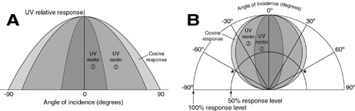
Figure 3. Rectangular (A) and Polar (B) plots of UV radiometers with different Angular Response. In polar coordinates the cosine response is a perfect circle. A UV sensor with an ideal cosine response and a 60 degree angle deviation from the UV source, the intensity of the UV detected should read 50% of the maximum value (see asterisk signal in plot B).
For radiometers monitoring a single lamp, a unit with a narrow spatial response focused on the lamp being monitored will be more sensitive than a unit with wide spatial response (Figure 4).
The Axial Symmetry is a measure of how symmetrical is the “cone of view” along the axis perpendicular to the window surface.
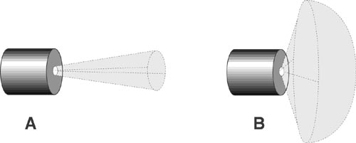
Figure 4. Schematics for two radiometers with different spatial
response. Both units have similar axial symmetry, however Radiometer A
has a narrow angular response, useful for monitoring a single lamp,
especially in reactors with more than one lamp in which the ratio
radiometer:lamp is 1:1. Radiometer B has a wider angular response
allowing it to measure simultaneously multiple UV sources. Although the
“cone of detection” of sensor B is wider, the sensor response to a UV
source located in front of the window will be maximum, while the same
lamp located near the “edge of the cone” will have a smaller response
level.
Optical Attenuation: The diffuser may be used to decrease the UV irradiance levels that will be measured by the photodetector. This is used in high-irradiance UV systems, wherein decreasing the irradiance levels may potentially avoid response saturation of the photodetector and, depending on the type of photodetector selected, it may prevent premature photodetector degradation. A diffuser with attenuation properties should be validated in the full operational range of the UV system to certify that the attenuation will not modify the spectral sensitivity or affect the linearity of the response of the sensor.
Focusing Optics: The focusing optics unit consists of one or more lenses that converge the incoming UV radiation into the photodetector. The optical design of the focusing system will dictate how efficiently the incident UV radiation is transmitted to the photodetector.
Filter: Filters are used to block certain parts of the radiation spectrum that may interfere with the monitoring process. There are many types of filters, all of them with different advantages and disadvantages. Ideally, the responsivity of the photodetector selected will cover only the wavelength range to be monitored (Figure 5).
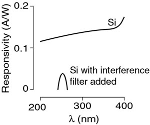
Figure 5. Responsivity plot of a silicon
photodiode with and without filter for specificity at
254 nm. Note the loss in responsivity when the filter is used.
If the selected photodetector is not very selective, the use of filters may be appropriate. However, although many see the use of filters as a clean and easy solution to fix the photodetector selectivity to the electromagnetic spectrum, adding a filter to a radiometer requires careful examination of potential problems. Some problems of using certain filters include delamination and other filter failures over time, especially if the unit will be cycled at wide temperature range; loss of responsivity; decreased transmission of selected wavelength range over time (translated in signal loss); wavelength shift at different angles; and high cost.
3-ELECTRONIC SIGNAL-PROCESSING MODULE: Comprised of the UV Photodetector, the Sensor Electronics and the Controller or the Programmable Logic Controller (PLC) unit(s).
UV photodetector: There are many UV sensing options available. The selection of the right photodetector is probably the most important decision when a monitoring unit is developed.
Commonly used UV photodetectors for UV air or water treatment include:
Phototubes: These are special vacuum tubes with a cathode sensitive to light. Special components on their cathodes make these devices more sensitive to the UVC area. They have excellent sensitivity with good linearity, dynamic range and stability. However they have poor ambient noise performance (“dark current”), their vacuum glass bodies are fragile, they are susceptible to vibration (microphonic noise) and to electromagnetic fields (like the ones generated by UV lamp ballasts); some units require cooling or high voltage. In addition, they are relatively large in size and expensive. Their use for monitoring air or water UV treatments is rare.
Photodiodes: These are radiation-sensitive semiconductors manufactured in the same way as diodes, in which basically the surface of the chip, which is sensitive to some part of the electromagnetic spectrum, is larger and exposed to the radiation source. Photodiodes have many advantages including low cost, very good sensitivity, stability and dynamic range. In addition they have excellent linearity, reproducibility and ruggedness. Today photodiodes are the most common choice for UV air and water monitoring systems.
Depending on the material used to manufacture the semiconductor, the photodiode will have a different response in a given area of the UV spectrum (Figure 6). Standard materials include Silicon, Silicon Carbide (SiC), Gallium Nitride (GaN) and Aluminum Gallium Nitride (AlGaN).
Silicon photodiodes are probably the most common sensors used for UV monitoring. However, they have a broad response from 200 nm to 1,100 nm covering the entire UV, visible and infrared spectra. If the UV source emits radiation outside the germicidal range (200 to 300 nm with the peak at 260 nm) or if other radiation sources are present where the sensor is located (i.e.: visible light sources in upper room air UV treatment), the use of filters is recommended. In addition, silicon photodiodes degrade after a few hundred hours of exposure to 10 mW/cm2 at 254 nm, making them less than the ideal choice for continuous monitoring. SiC, AlGaN and GaN photodiodes are specifically designed to measure emissions in the UV range.
For each wavelength, a photodiode has a specific efficiency to convert the intensity of the radiation at this wavelength (Watts) into an electrical response (Amperes). This efficiency is known as Responsivity of the photodiode. Plotting Responsivity versus Wavelength shows how well a photodiode responds to a given range of the radiation spectrum:
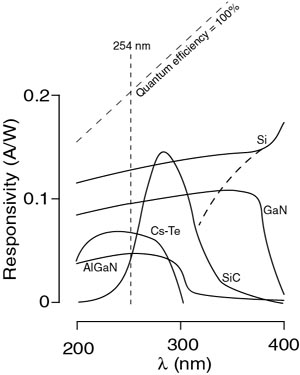
Figure 6. Response curve of different types of photodiodes: Si
(regular –dotted line- and UV enhanced), AlGaN, GaN and SiC and of Cs-Te
coated phototube
Common UV radiation sources used for water and air treatment include low4 - and medium-pressure mercury lamps, and pulsed Xenon lamps5 (Figure 7). These sources have different radiation intensities for each wavelength
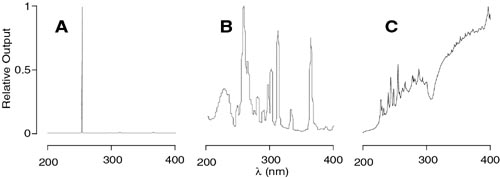
Figure 7. Relative output spectra of three different types of UV
lamps:
A-Low-pressure Mercury lamp, B-Medium-pressure Mercury lamp, and
C-Pulsed Xenon lamp
It is important to understand that the overall response of a sensor system to a particular UV source is given by the output spectrum of the source and the response curve of the sensor (in turn given by the response curve of the photodetector used with filter(s), diffuser and any other optical components that may modify the radiation reaching the photodetector)
Avalanche Photodiodes: For low irradiance levels, avalanche photodiodes combine the excellent sensitivity of the phototubes with the ruggedness of the photodiodes. Their cost is high, they have higher dark current than photodiodes and require special electronics to provide a regulated power supply and temperature control. They are used in special applications where the sensitivity of commercially available photodiodes is not high enough to monitor low irradiance levels.
Sensor Electronics. The design of the electronics that process the signal created by the photodetector is very important. Depending on the required time response, noise background, irradiance levels, type of photodetector used and other factors, the electronics maybe designed in many different ways.
Photodiodes can be used in photovoltaic mode (with no power supply, similar to a solar panel), or in photoconductive mode (with external power supply). Each mode has its own advantages and disadvantages.
In most cases the electronics enclosed in the sensor body amplify the signal output of the photodetector and, if necessary, convert it into voltage or into current. Depending on the type of Controller that will receive this signal, how far from the sensor it is located, required linearity and range of detection and other requirements, the electronics should be designed to produce the appropriate output.
Sensor Calibration: All sensor systems require calibration against a reference standard. This calibration must be conducted periodically (once a year is common) by a facility with documented procedures and traceability program to a recognized reference source. If the Sensor can be disconnected from the Controller, the calibration adjustment should reside in the Sensor Electronics and NOT in the Controller. A good design incorporates the calibration into the sensor body, thus eliminating the potential problem of connecting a Sensor to the wrong Controller.
Temperature Variation: Some photodetectors change their response signal with changes in temperature. If the UV process has a wide temperature variation, the measure of the temperature of the sensor can be used to correct variations in the photodetector response. This correction can be made at the Sensor level or at the Controller level. If the latter is selected, the cable connecting the Sensor to the Controller must carry not only the UV irradiance information, but also the temperature values.
Pulsed UV Sources: Xenon lamps produce UV radiation in pulses. With rates of 10 to 30 Hz (10-30 pulses per second), if the electronics of the sensor are not designed to measure these types of radiation sources, the readings may be underestimated. Depending on the pulse duration and the time between pulses, the radiation the error in the measurements will vary.
Controller / PLC Units. The Controller is the part of the on-line radiometer that shows UV radiation levels and allows the user to regulate different outputs to achieve the proper monitoring level. Depending on the complexity level of the UV system being monitored, the Controller may include any of the following features:
Irradiance Level Display: Normally expressed in µW/cm2 or mW/cm2. Some systems express the irradiance levels in percentage units, being 100% the adjusted level when the a new lamp(s) is(are) installed. Although simple to understand, the systems reporting irradiance levels only in percentage mode cannot be trusted to monitor the efficiency of the UV-driven process precisely. Changes in lamp manufacturer, quartz sleeve degradation, water turbidity, presence of compounds that absorb in the UV region, etc., are all factors that potentially may affect the 100% lamp setting if present and not corrected during the lamp replacement. Easy to monitor daily, the percentage output or the green/yellow/red lights system are convenient, but do not provide an absolute reading. A Controller always must have the ability to produce an absolute output in irradiance units.
Irradiance level outputs: Similar to the display level, they provide absolute and relative output in different formats (0 to 1 Volt, 4 to 20 mA, digital RS232, etc.) for remote monitoring units, integration to SCADA systems, or connection to PLCs for advance control process (i.e., flow control based on Irradiance levels, UV lamp power management, preventive lamp replacement based on Irradiance decrease over time).
Alarms: Relay-triggered outputs in the Controller allow the user to connect from a simple audible alarm to an automatic shutoff system to avoid untreated fluid going through the reactor when the UV Irradiance level falls below a preset value.
UV Dose: The on-line radiometers cannot determine the UV dose by integrating the irradiance for a period of time simply because the unit is fixed and does not travel through the reactor. However, certain on-line units may receive input from a flow meter and estimate the actual UV dose based on the flow value and the Irradiance level. The algorithm used and the values reported in this case must be validated during the reactor validation.
SUMMARY
The numbers of elements that constitute an accurate on-line radiometer are many. The proper selection and design of the unit creates a cost-effective system that monitors the UV process with adequate accuracy.
The design of the system must consider many elements of the UV process, including type of UV source, number of UV sources, type and properties of the fluid being treated, irradiance values, size and shape of the reactor, flow, etc..
As discussed previously, an on-line radiometer is a tool to monitor the performance of the UV process. However, the efficiency of the process must be long-established with a proper validation of the UV unit6. Placement of the radiometer in the “coldest possible spot” (usually the farthest point from any UV source) will allow detection of changes in UV transmission and other deterioration causes more precisely. The use of Computational Fluid Dynamics (CFD) during the design of the UV reactor may help to locate the ideal placement of the UV monitor. In some cases the reactor is already designed and installed and the only option is to identify the best possible place to install the sensor. This situation is seen commonly in the HVAC UV air treatment units where existing units are retrofitted with UV lamps. In this scenario, understanding the air flow and the Spatial Response of the Sensor will allow pinpointing the best location.
It is important to determine absolute irradiance values during the validation of the unit. These values will be used to determine what irradiance values will indicate the yellow and red alert lines for that particular system. A validation of the sensor in multiple-lamp units will also determine the weight of each lamp in the total sensor displayed irradiance value.
Finally, the knowledge of the Sensor Uncertainty will allow the user to utilize the sensor output data objectively, creating a system that truly provides the right tool for a coherent preventive maintenance program of the UV treatment system.
ACKNOWLEDGMENTS
The authors would like to thank the following people/companies for
providing data used in this manuscript:
Dr. Jim Bolton, for his comments and corrections during the preparation
of this manuscript.
Calgon Carbon Corporation – http://www.calgoncarbon-us.com
LightStream Technologies, Inc. – http://www.lightstreamuv.com
Philips Lighting V.B., The Netherlands – http://www.uvdisinfection.philips.com.
Steril-Aire, Inc. – http://www.steril-aire-usa.com
REFERENCES
§ Why cosine? Consider a UV source pointing at a sensitive area of a
sensor. When the sensitive surface of the sensor is facing the UV source
(0 degree angle), the position of the UV-sensotive area of the sensor is
maximized with respect tot he UV source. If the sensor is rotated, its
UV-sensitive area exposed to the sensor will decrease proportional to
the cosine of the angle of rotation.
1Bolton,
J.R. (2001) Ultraviolet Applications Handbook, 2nd Ed., Bolton
Photosciences Inc., 628 Cheriton Cres.,NW, Edmonton, Ab, Canada T6R 2M5.
2Bolton, J.R. (2002) New Developments in UV Photolysis and
Advanced Oxidation, Proceedings, First Asia Regional Conference of
Ultraviolet Technologies for Water, Wastewater & Environmental
Applications, CDROM, International Ultraviolet Association, PO Box
1110, Ayr, ON, Canada NoB 1E0.
3Stowe, R.W. (2001) Radiometric Methods for UV Process Design
and Process Monitoring, Proceedings, RadTech Europe.
4Giller, H.F. (2002) UV sources: improvements in medium
pressure mercury lamp technology. Proceedings, First Asia Regional
Conference of Ultraviolet Technologies for Water, Wastewater &
Environmental Applications, CDROM, International Ultraviolet
Association, PO Box 1110, Ayr, ON, Canada NoB 1E0.
5UV News (2000) Thematic Network for Ultraviolet
Measurements, Characterizing the Performance of Integral Measuring
UV-Meters, Issue 6 / Nov. 2002, Helsinki University of Technology,
Helsinki, Finland.
6USEPA (2003), Ultraviolet Disinfection Guidance Manual. EPA
Report No. 815-D-03-007, June 2003 Draft. Office of Water, US EPA,
Washington, DC. http://www.epa.gov/safewater/lt2/guides.html.
Room 1019, Nan Fung Comm. Ctr., 264-298 Castle Peak Road, Tsuen Wan, N.T. Hong Kong
香港新界青山道264-298号南豐商業中心1019室
Tel 电話: (852) 2611-7376 Fax 傳真 : (852) 2617-5716 E-Mail电郵 : envirohk@netvigator.com